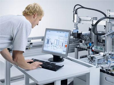

A Programmable Logic Controller, PLC or Programmable Controller is a digital computer used for automation of electromechanical processes, such as control of machinery on factory assembly lines, amusement rides, or light fixtures. The abbreviation "PLC" and the term "Programmable Logic Controller" are registered trademarks of the Allen-Bradley Company (Rockwell Automation)
PLCs are used in many industries and machines. Unlike general-purpose computers, the PLC is designed for multiple inputs and output arrangements, extended temperature ranges, immunity to electrical noise, and resistance to vibration and impact. Programs to control machine operation are typically stored in battery-backed-up or non-volatile memory. A PLC is an example of a hard real time system since output results must be produced in response to input conditions within a limited time, otherwise unintended operation will result.
Early PLCs were designed to replace relay logic systems. These PLCs were programmed in "ladder logic", which strongly resembles a schematic diagram of relay logic. This program notation was chosen to reduce training demands for the existing technicians. Other early PLCs used a form of instruction list programming, based on a stack-based logic solver. Modern PLCs can be programmed in a variety of ways, from the relay-derived ladder logic to programming languages such as specially adapted dialects of BASIC and C. Another method is State Logic, a very high-level programming language designed to program PLCs based on state transition diagrams. More recently, PLCs are programmed using application software on personal computers.
The computer is connected to the PLC through Ethernet, RS-232, RS-485 or RS-422 cabling. The programming software allows entry and editing of the ladder-style logic. Generally the software provides functions for debugging and troubleshooting the PLC software, for example, by highlighting portions of the logic to show current status during operation or via simulation. The software will upload and download the PLC program, for backup and restoration purposes. In some models of programmable controller, the program is transferred from a personal computer to the PLC through a programming board which writes the program into a removable chip such as an EEPROM orEPROM.
PLCs have built in communications ports, usually 9-pin RS-232, but optionally EIA-485 or Ethernet. Modbus, BACnet or DF1 is usually included as one of the communications protocols. Other options include various fieldbuses such as DeviceNet or Profibus. Other communications protocols that may be used are listed in the List of automation protocols. Most modern PLCs can communicate over a network to some other system, such as a computer running a SCADA (Supervisory Control And Data Acquisition) system or web browser.
PLCs used in larger I/O systems may have peer-to-peer (P2P) communication between processors. This allows separate parts of a complex process to have individual control while allowing the subsystems to co-ordinate over the communication link. These communication links are also often used for HMI devices such as keypads or PC-type workstations.
Discrete signals behave as binary switches, yielding simply an On or Off signal (1 or 0, True or False, respectively). Push buttons, Limit switches, and photoelectric sensors are examples of devices providing a discrete signal. Discrete signals are sent using either voltage or current, where a specific range is designated as On and another as Off. For example, a PLC might use 24 V DC I/O, with values above 22 V DC representing On, values below 2VDC representing Off, and intermediate values undefined. Initially, PLCs had only discrete I/O.
Analog signals are like volume controls, with a range of values between zero and full-scale. These are typically interpreted as integer values (counts) by the PLC, with various ranges of accuracy depending on the device and the number of bits available to store the data. As PLCs typically use 16-bit signed binary processors, the integer values are limited between -32,768 and +32,767. Pressure, temperature, flow, and weight are often represented by analog signals. Analog signals can use voltage or current with a magnitude proportional to the value of the process signal. For example, an analog 0 - 10 V input or 4-20 mA would be converted into an integer value of 0 - 32767.